| Publication Type | Miscellaneous |
| Source | (undated) |
| Keywords | tools |
INTRODUCTION
Panasonic 3130 1/2" editing deck
Reproduced from an undated Operating Instructions manual, published by Matsushita Electric Corporation of America.
Features
Specifications
Functions of Major Operating Components
Panasonic's Model NV-3130 is designed to the exacting specifications of the new EIAJ recommended color standard and is fully compatible with EIAJ 1 standard for recording and playback in black and white. The Panasonic assembly mode editing system permits synchronized, roll-free incorporation of sequences from a variety of sources onto prerecorded tape. The NV-3130 editing system allows you to achieve thoroughly professional results; the playback signal from the recorded tape is locked to the incoming sync or composite signal by the capstan servo system so that editing can be performed without loss of vertical sync. In addition, the NV-3130 features HPF* heads for longer head life and higher picture quality, an inscribed head drum for sure interchangeability, and even a dropout/noise compensator that virtually eliminates dropouts from 3" tape. The NV-3130 is a lightweight, compact and economical 3" color recorder that allows even the most budget conscious institution or government agency to make the important change to color and still maintain full capacity for recording and playing back tapes on the ElAJ^i black and white standard. Even tapes recorded in color can now be played back on black and white machines of the Panasonic NV-3000 series or any other EIAJ #1 standard machine. The NV-3130 uses standard 2" video tape for added economy. Special features include perfect electronic editing, slow motion, an audio dubbing facility, still framing, and automatic color lock control. The NV-3130 provides more than 240 lines of horizontal resolution in color and better than 300 lines in black and white. Its ease of operation and quality construction make the NV-3130 the logical choice for almost any governmental, institutional or educational closed circuit television application.
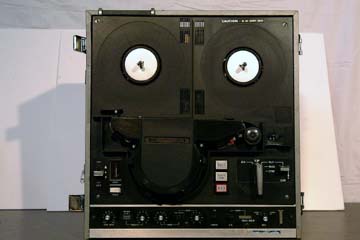
NV-3130 top
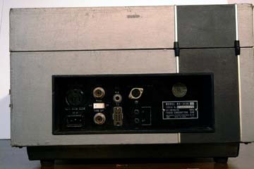
NV-3130 back
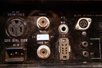
NV-3130 back inputs
FEATURES
1. EIAJ Recommended Standard 1/2" Color and EIAJ #1 B/W.
2. Built-in color capability.
3. Fully electronic servo editing.
4. HPF* heads afford extra long head life and high picture quality.
5. New Panasonic technology allows incorporation of a dropout/noise compensator that virtually eliminates dropout.
6. Electronic editing permits instant editing of audio and video information from camera, monitor TV or prerecorded tape.
7. Stop action and slow motion playback.
8. Simple tape threading.
9. Precision inscribed tape path on head drum insures 100% tape interchangeability with all Panasonic NV-3000 series VTRs.
10. Audio dubbing.
11. Skew (back tension) control.
12. 1 hour playback and record capability.
13. RF modulator (optional) for playback on conventional TV sets.
14. Automatic color indicator light verifies presence of color.
SPECIFICATIONS (NV-3130) (SUBJECT TO CHANGE WITHOUT NOTICE)
Power Source: AC 120 V, 60 Hz
Power Consumption: Approx. 90 Watts
Video Recording System: 2 rotary heads, EIA standard (525 lines, 60 fields)
Video Modulation System: Both sideband FM
Tape Speed: 7-1/2 i.p.s.
Reel Size: 7 inches
Tape Width: 1/2 inch
Heads: Video: 2 rotary heads
Audio/control: 1 stationary head
Erase: 1 for both video and audio
Erase: 1 for audio dubbing
Recording Time: 63 min. with NV-P71 (2,400 ft.)
Horizontal Resolution: B/ W more than 300 lines
(on Monoscope Test Pattern) Color more than 240 lines
Active Elements: Fully transistorized
Frequency Response: Video: Greater than 2.5 MHz
Audio: 8010,000 Hz
Signal-to-Noise Ratio: Video: B/W better than 40 dB
Audio: Better than 40 dB
Input Level: Video: Min. 0.5 Vp-p
Audio: MIC 0.001 V (-60 dB)
AUX 0.1 V (-20 dB)
Input Impedance: Video: 75 ohms unbalanced
Audio: MIC 20 K ohms unbalanced
AUX 1 M ohm unbalanced
Output Level: Video: 1.0 Vp-p (0 dB)
Audio: 0.1 V (-20 dB)
Output Impedance: Video: 75 ohms unbalanced
Audio: 600 ohms unbalanced
Dimensions: 15-7/8" (W) x 16-3/4" (D) x 7-3/4" (H)
Weight: Approx.46 Ibs.
FUNCTIONS OF MAJOR OPERATING COMPONENTS
1. TENSION ARM
2. SUPPLY REEL
3. ROTARY VIDEO HEAD HOUSING
4. TAKE-UP REEL
5. RECORD BUTTON
By pressing the Record Button, both video and audio recording levels can be checked (shown on the Recording Level Meter (26)) without running the tape. To start recording, turn the Function Lever (12) to the PLAY position while holding the Record Button down.
6. AUDIO DUBBING BUTTON
To replace the audio recording with another, press this button and record. Refer to AUDIO DUBBING (page 18).
7. EDITING BUTTON
To edit the prerecorded program (picture and sound), simply push this button while playing back the tape. The prerecorded program, if any, will automatically be erased and replaced by the new recording. Refer to ELECTRONIC EDITING (pages 15-18).
8. CAPSTAN
9. TAPE COUNTER
10. TAPE COUNTER RESET BUTTON
This tape counter indicates the relative point of the tape and may be used for the future reference to the program recorded on the tape. To reset the counter to zero, push the Reset Button.
11. SLOW MOTION LEVER
To reproduce slow motion picture, turn the Function Lever 12 to the PLAY position, and then move the Slow Motion Lever in the arrowed direction until it gets locked.
12. FUNCTION LEVER
Turn this lever for REWIND, STOP, PLAY, PAUSE and FAST FORWARD.
* Always make sure the Function Lever is correctly positioned for mode desired and not half-way between positions.
* Always turn the Function Lever slowly with a deliberate pause at each mode to give the tape time to stop or start smoothly.
13. EDITING INDICATOR LAMP
Will light up only when a video signal comes in from a camera, a TV monitor or a video tape recorder through the Camera Input Receptacle (29) and when the Mode Selector (14) is set at either INSERT or ASSEMBLY EDIT position.
14. MODE SELECTOR
Allows selection of INSERT EDIT, ASSEMBLY or NORMAL. The NORMAL position is for normal recording and playback. The INSERT EDIT and ASSEMBLY EDIT positions are for electronic editing. See pages 15-18.
15. COLOR INDICATOR LAMP
Lights up when a color program is being recorded or played back.
16. COLOR-B/W SELECTOR
Selects black-and-white or color program.
17. TV-CAMERA SELECTOR
Selects the TV monitor (connected with the TV Monitor Receptacle (35) or the CCTV camera (connected with the
Camera Input Receptacle (29) as a recording source.
18. VIDEO RECORDING LEVEL CONTROLLER Turn this controller to control the video recording level.
19. RECORDING LEVEL METER SELECTOR Set the Recording Level Meter Selector at VIDEO, and the Recording Level Meter will work as a video recording level indicator; at AUDIO, the selector functions as an audio recording level indicator. Refer to the Recording Level Meter(26).
20. AUDIO RECORDING LEVEL CONTROLLER Controls the audio recording level and should be adjusted to have the Recording Level Meter (26) needle peak just below the red zone.
21. TRACKING CONTROLLER Turn this controller to remove the tracking noise in the picture which may appear when the tape recorded on another recorder is played back. Can be turned to the FIX position for tapes recorded on and played back on this unit. See page 13.
22. TRACKING METER Indicates when tracking control has been adjusted properly by maximum needle deflection.
23. SLOW MOTION SPEED CONTROLLER Controls the speed of the tape in the slow motion mode. The speed is variable from stop to 1/4 time the normal speed. Refer to the Slow Motion Lever (11).
24. POWER SWITCH
25. PILOT LAMP
The Pilot Lamp lights up when the power is on.
26. RECORDING LEVEL METER
Indicates audio or video recording level. Refer to Recording Level Meter Selector (20 ) and RECORDING (pages
10-11).
27. SKEW CONTROL LEVER Playback image distortion in the upper portion of the monitor screen can be eliminated by adjusting this control. See page 14.
28. AC OUTLET This outlet may be used to supply AC power (120 V, 60 Hz) to a CCTV camera, a TV monitor or other equipment which requires AC power. The maximum wattage is 300 W.
29. CAMERA INPUT RECEPTACLE
For connection with the video output connector on a Panasonic CCTV camera (optional).
30. MIC INPUT JACK
For connection with a microphone (optional). High impedance (20 k ohms).
31. APC (AUTOMATIC PHASE CONTROL)
Factory pre-adjusted. Refer adjustment to qualified service personnel only.
32. COLOR TV CONTROL RECEPTACLE Connected with the V. SYNC receptacle on the Panasonic Color TV Monitor CT66N (M) only, using the optional color TV control cable (Part no. VEC5009).
33. AUDIO OUTPUT JACK
For connection with an audio input jack on a TV monitor, or an external power amplifier or a speaker system.
34. AUDIO INPUT JACK
For direct recording from auxiliary sound source, such as radio tuner, hi-fi system, audio tape recorder, etc.
* When using this recording method, make sure that the volume control on the external sound source is set at a low level. Over-driving this input may result in damage to the preamplifier circuit.
35. TV MONITOR RECEPTACLE
For connection with a TV monitor using the attached 8-pin VTR-monitor connection cable.
36. VIDEO OUTPUT RECEPTACLE
For playback on a TV monitor.
37. MOTOR STAND-BY SWITCH
The Motor Stand-by Switch is designed to start the head motor if the Function Lever 12 is in the STOP position.
To start the motor, press the Record Button J and turn on the Motor Stand-by Switch. See page 11.
38. AC POWER INPUT RECEPTACLE
For connection with the attached AC power cord (VJA33).