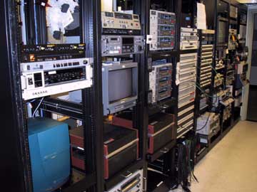
Overall configuration
The following is the logic behind BAVC's setup:
- Tape machines must be centrally located so tapes can be easily switched from one playback machine to another. If you put a tape on an AV-8650 and after some playback you realize it is a "skip-field" tape, the CV-2100 must be close at hand and ready to playback the tape. If playback of an EIAJ tape is a problem on AV-8650 switching to a second AV-8650 may improve playback due to tape interchange problems since all AV-8650s seem to playback a little differently, or because of differences in maintenance of the two AV-8650s.
- Viewing the signals through the different signal paths must be accomplished with a minimum of re-patching. You should be able to troubleshoot the playback of a tape by switching playback tape machines or TBCs, rather than re-cabling.

With these two design requirements, BAVC's remastering center is connected in this way:
1. Playback tape machines
- First in the signal flow are the 2 AV-8650s, the CV-2100 and the BVU-800.
2. Audio/video switcher
- Each playback machine is connected to one of the inputs of the A/V switcher.
- The video output of the A/V switcher is connected to the input of a Video Distribution Amplifier (VDA)
- The audio output of the A/V switcher is connected to 2 patchpoints on BAVC's control room audio patchbay
3. Video output of VDA
- The video output of the VDA is sent to each TBC, the full frame DPS TBC IV and the 16 line BVT-810.
- An uncorrected video signal (does not go through a TBC) from the VDA is sent directly to color monitor input B. If there is any question about the affect a TBC is having on a signal the operator can press a button on the color monitor to view the uncorrected signal as a reference.
4. Outputs of the TBCs
- The outputs of the two TBCs are connected to patchpoints on BAVC's control room video patchbay.
5. Video patchbay
- The selected video signal is patched to the VDA.
6. VDA and audio to recorder
- The video signal from the VDA and the audio signals are patched to the record tape machine.
7. VDA to waveform monitor/vectorscope
- The video signal from the VDA is patched to the remastering center's waveform monitor/vectorscope.
8. Color monitor A input
- The video monitor output from the waveform monitor/vectorscope is sent to the A input of the color monitor. From the control panel of the waveform monitor/vectorscope, the video sent to the A input (waveform monitor, vectorscope, color picture, mix) can be selected.
9. Advanced sync from BVT810
- The advanced sync output of the BVT-810 TBC is sent to the two AV-8650s video inputs and to the BVU-800's "sync in" using BNC barrel connectors.
Appendix 12.2 shows block diagram of the signal flow in the system.